What is a Level Transmitter?
Submersible sewage or sump pumps are mounted inside a basin to remove liquid once it reaches a designated level in the basin. The pump is directed to start pumping by its control panel. A Programmable Logic Control (PLC) panel can be designed to receive signals from a submersible Level Transmitter, Float/Diaphragm Micro Switches or Both.
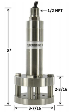
A submersible level transmitter (Figure 2) may consist of a piezoresistive sensing element encased and sealed in a housing. The sensing element is designed with a ventilation tube in the cable to compensate for changes in atmospheric pressure above the basin.
The level transmitter is typically hung from the cover or a wall bracket and placed at or near the bottom of the basin. Fluid pressure acting on the piezoresistive element sends a signal to the panel which represents the depth of the fluid. The PLC panel starts or stops the lead or lag pump, or generates an alarm based on the fluid depth. The level at which these actions are taken can be adjusted at the panel. This provides flexibility not possible with traditional analog switches positioned during installation.
However some systems require redundancy due to the sensitive location of the basin and the area it supports. In these cases Failsafe Float positioning is desirable.
Why Use Failsafe Floats?
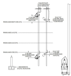
Figure 1 depicts a common duplex pit configuration. The stop, lead, lag and high water levels are identified. These levels are entered in the PLC panel and will be activated when the level transmitter indicates the fluid has reached these levels.
However if the level transmitter were to fault or be damaged by some unforeseen event, it would be desirable for a secondary circuit to engage if the fluid level were to exceed the levels programmed in the panel.
Failsafe float positioning circuits consist of two analog relays which are wired to float or diaphragm micro switches mounted outside the stop, lead, lag, high water alarm window represented in the PLC panel. The floats are positioned to activate in the event the fluid level occurs outside the level transmitter window. The lower switch stops all pumps. The upper (high water) switch starts all pumps. This second level of protection avoids issues from an unforeseen event at the level transmitter.